Neat, switching to the ItsyBitsy just... works
This article is part of a series.
- Part 1: Hello LED on an AVR (ATtiny45) in C
- Part 2: How can I make programming an ARM chip as hard as possible?
- Part 3: How can I get this SAMD21E18 startup code a little sturdier?
- Part 4: It's ALIVE! (SAMD21E18A, Assembly, No SDK)
- Part 5: And now for 3 ways to set an internal pullup
- Part 6: It'd make sense to do some toolchain clean up
- Part 7: This Article
Related Repo: https://github.com/carlynorama/StrippedDownChipRosetta/tree/main/ARM/SAMD21G18A/01_AssemblySwitch
The ItsyBitsy
Switching to the ItsyBitsy from the Trinket means means I’ll able to do a breadboard circuit without worrying about smooshing the fragile little solder joints on the bottom for the programmer. (With normal Trinket usage that wouldn’t be a problem because normal sensible people use the UF2 bootloader capabilities.) The ItsyBitsy uses the SAMD21G18A instead of the SAMD21E18A, requiring some minor tweaks to the code. todbot already had one all soldered up with the headers and I snicked it.
- https://learn.adafruit.com/introducing-itsy-bitsy-m0
- https://learn.adafruit.com/introducing-itsy-bitsy-m0/downloads
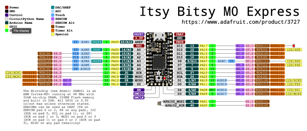
- https://learn.adafruit.com/introducing-itsy-bitsy-m0/pinouts
Differences between E and G
Screenshot of the pinout diagram of the SAMD21G18A (5.2.1 in family datasheet)
The G has more pins than the E. That doesn’t matter much to this project except the vector table gets two new peripherals added back in: SERCOM4, SERCOM5. See the new startup.s [TODO LINK]
To figure out what peripherals changed, I looked at the Configuration Summary (Section 2-1, page 14 in the Family Datasheet).
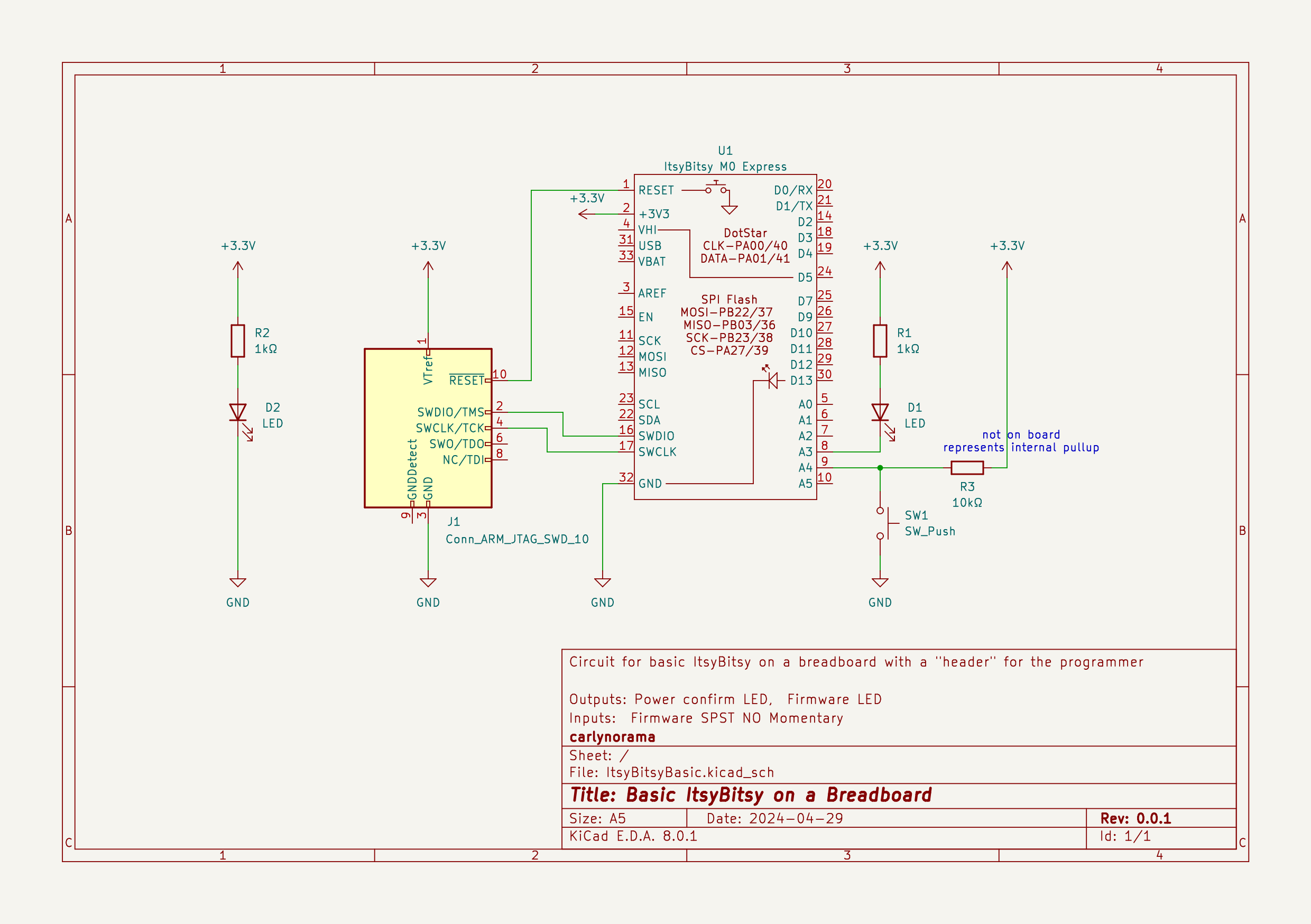
Making the Circuit
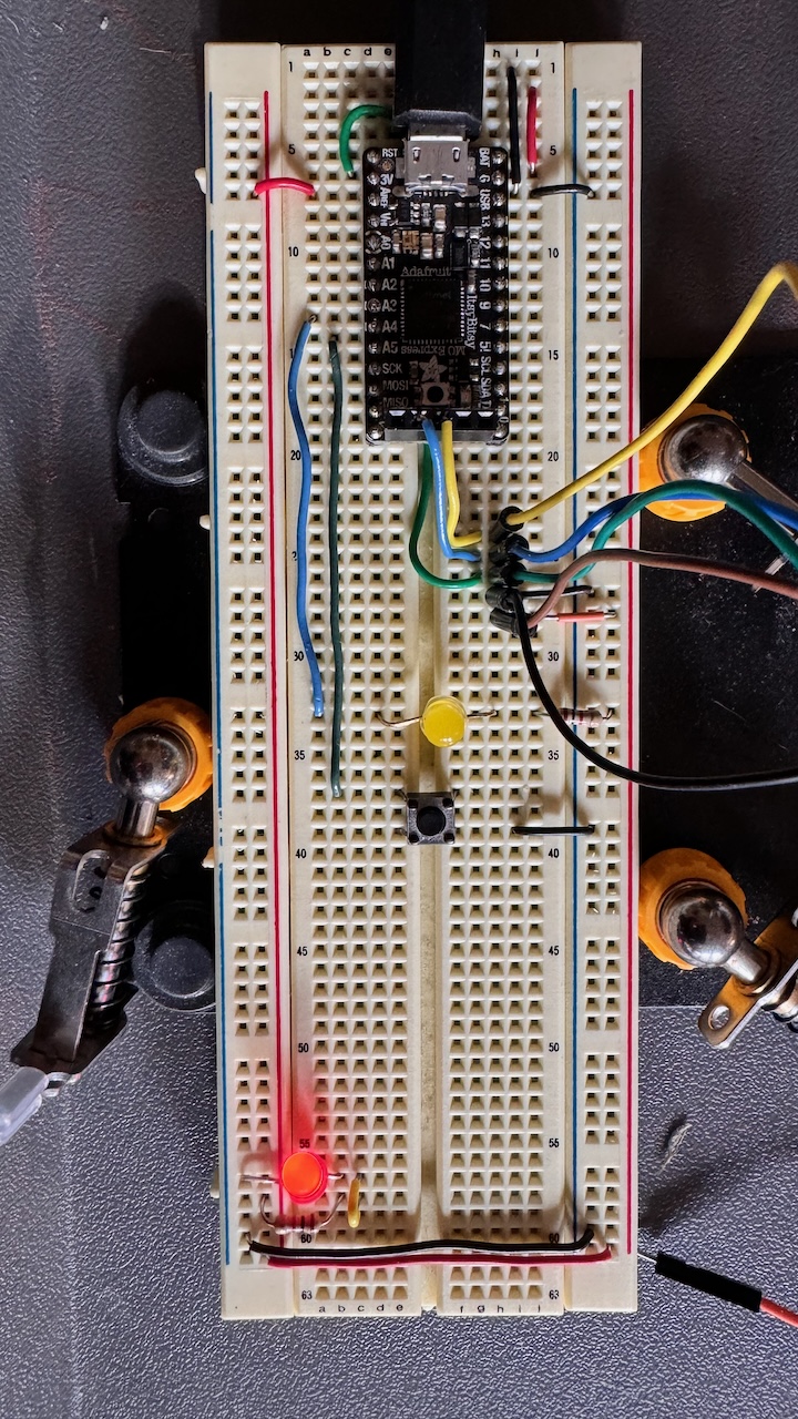
Unlike the bare ATTiny, I don’t have to make the voltage regulator part of the circuit because the ItsyBitsy already has one. I just pulled the 3.3V and the GND into the breadboard buses. Otherwise it is pretty much the same, with extended wires out to a pseudo-header for the J-LINK.
(The red and black wire up on the top right are there as another pseudo-header for providing non-USB power. I left them off the schematic )
- switch pin: ItsyBitsy A4 / Chip PA05
- led pin: ItsyBitsy A3 / Chip PA04
Updating the Code
Not really much to do.
The Makefile
line 7
CHIP ?= SAMD21G18A
startup.s
lines 41, 42
    .word   SERCOM4_Handler
    .word   SERCOM5_Handler
lines 88, 89
.weakref SERCOM4_Handler, default_handler
.weakref SERCOM5_Handler, default_handler
main.s
step 1
lines 17, 18
.equ ledPinOffset, 4    //PA04, "A3" on ItsyBitsy
.equ switchPinOffset, 5  //PA05, "A4" on ItsyBitsy
This works but the logic is inverted now, LED is on, unless the button is pressed, so lines 73 and 77 also need to be swapped, resulting in:
  ledOff:  //default path
    STR R3, [R5] //R3==ledMask, R5==portA_OUTSET
    B loop

  ledOn:
    STR R3, [R6] //R3==ledMask, R6==portA_OUTCLR
    B loop
and… done! It works!

Summary
So these two chips come from the same family so it’s not too much of surprise the transition went smoothly. The real test of the Arm promise will be sharing code between one of these M0+ and a chip with a different Coretex-M rating. To do that it would make sense to be working up in the C so the compiler can handle rendering the different appropriate assembly code. A mixed C/Assembly project’s the next step!
This article is part of a series.
- Part 1: Hello LED on an AVR (ATtiny45) in C
- Part 2: How can I make programming an ARM chip as hard as possible?
- Part 3: How can I get this SAMD21E18 startup code a little sturdier?
- Part 4: It's ALIVE! (SAMD21E18A, Assembly, No SDK)
- Part 5: And now for 3 ways to set an internal pullup
- Part 6: It'd make sense to do some toolchain clean up
- Part 7: This Article